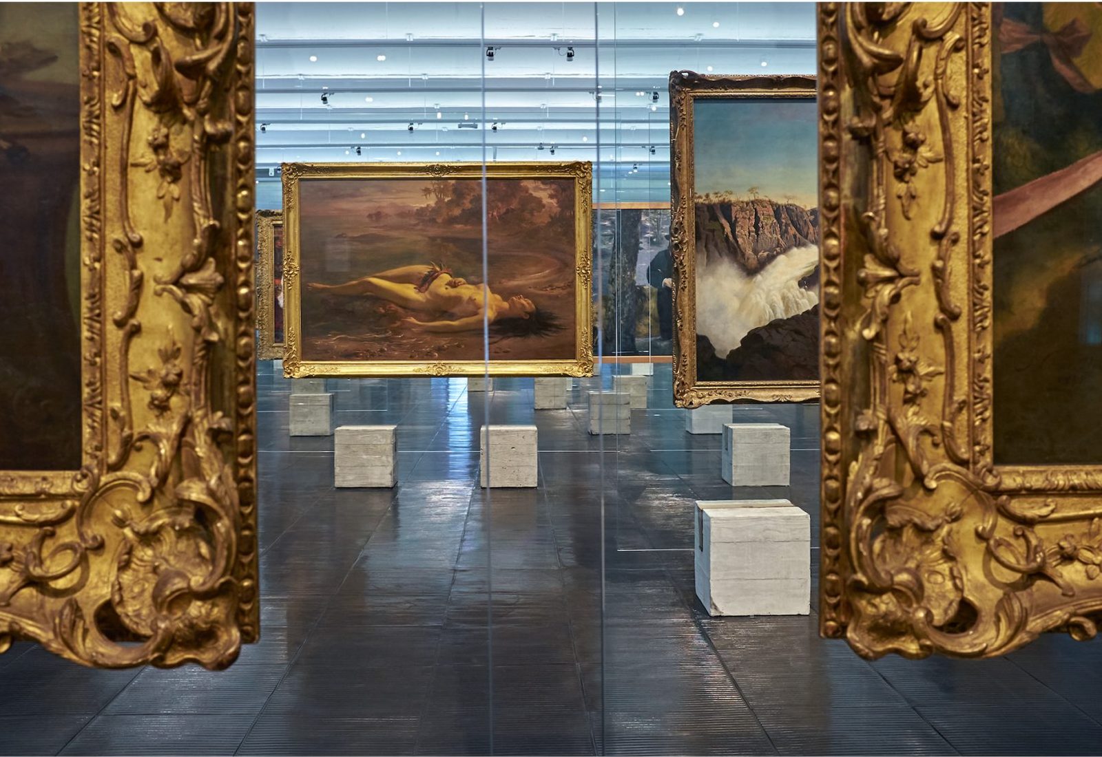
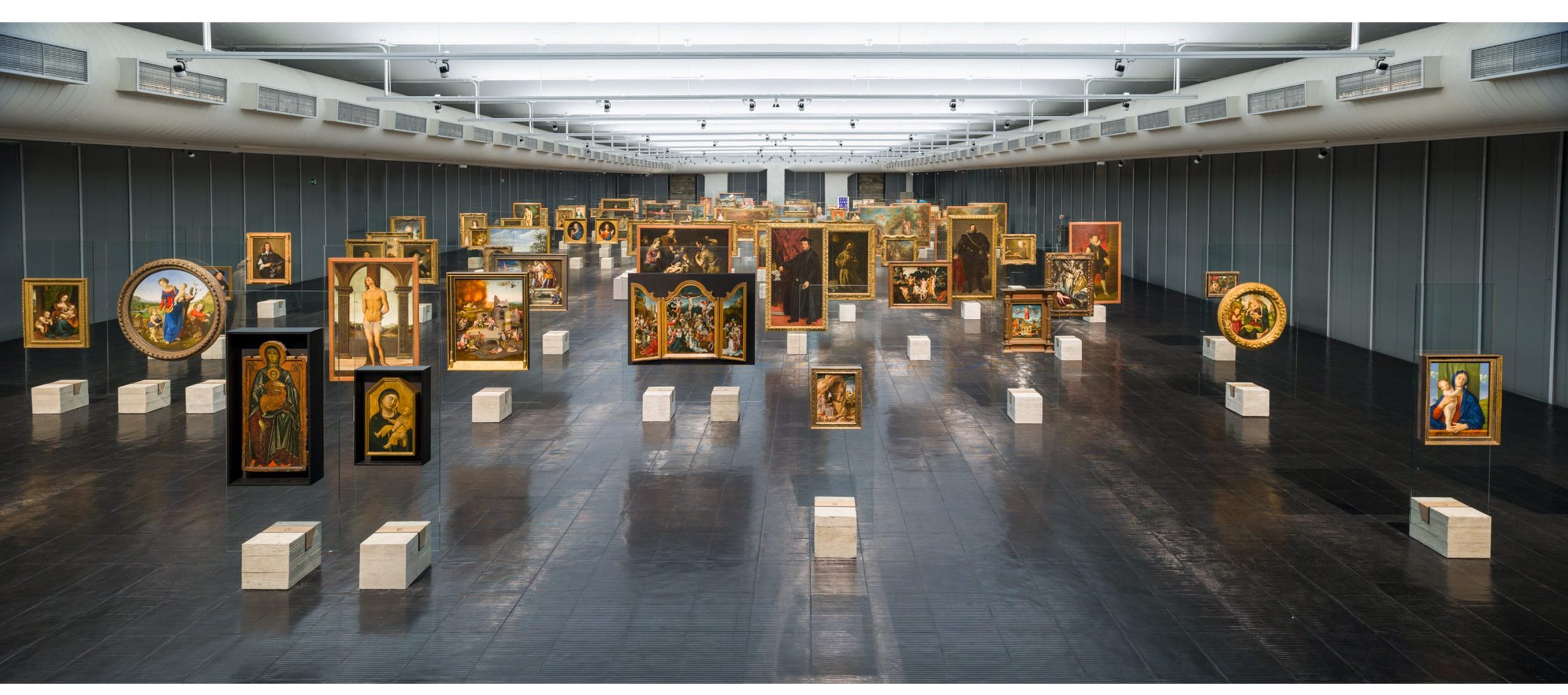
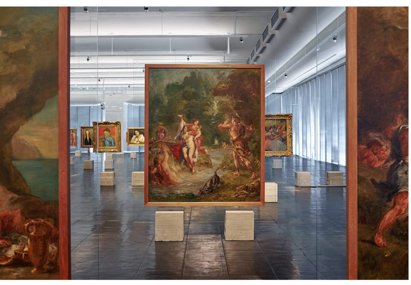
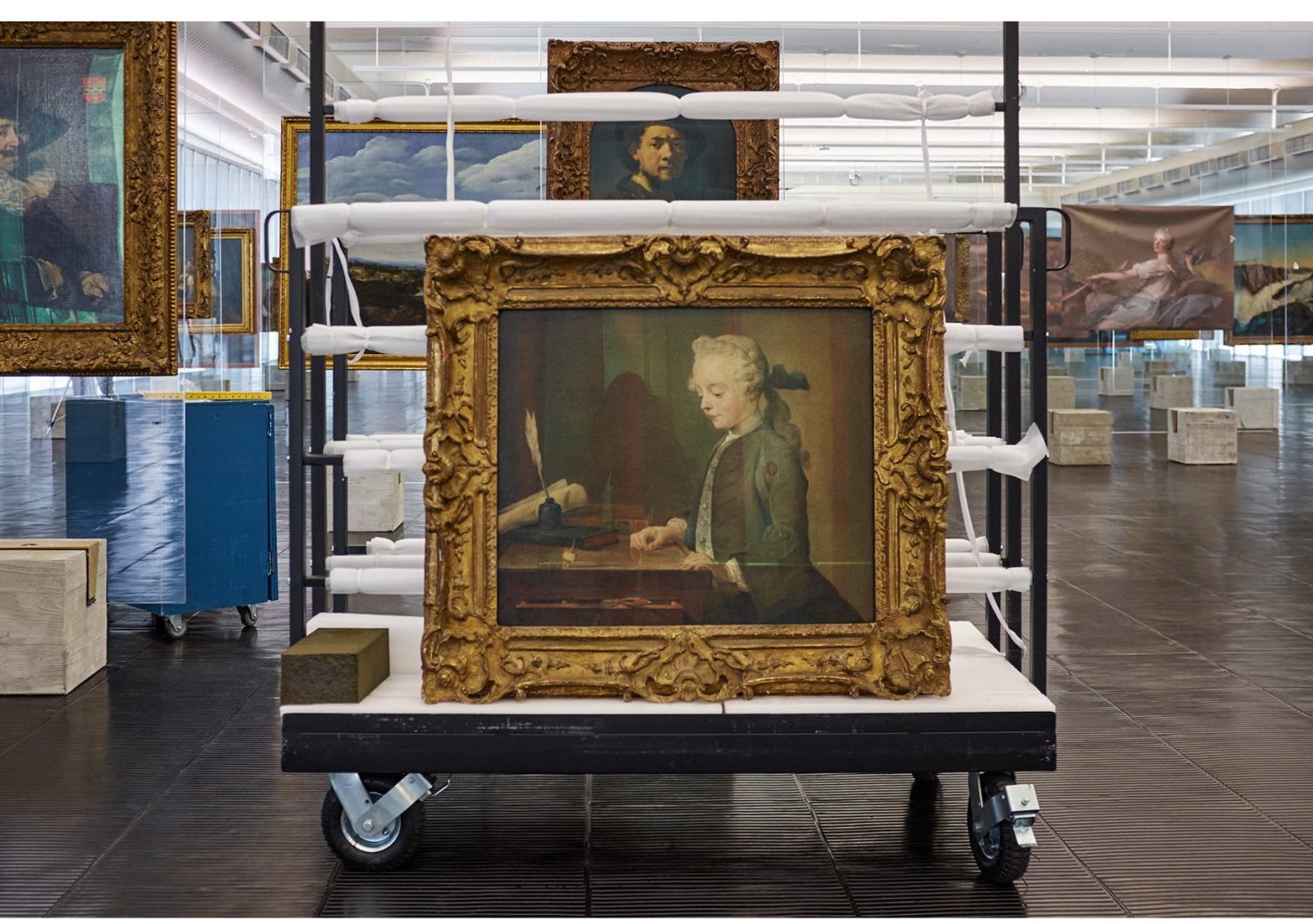
Although the main discussion surrounding the crystal easels was of a different nature, technical and safety aspects prevailed and became the official arguments for their dismantling. After nearly twenty years out of the Masp, they return to the exhibition in a reconstruction that pays special attention to these same technical aspects. With these technical concerns now resolved, it will be possible to revisit and reevaluate the original intentions, their effects, and their brilliant formalization — the almost total dematerialization of the support, paradoxically achieved through rudimentary technique and expressive materiality, a recurring mechanism in Lina Bo Bardi’s poetics. The crystal easels can be considered part of the museum’s collection and heritage, not only because of their importance in the history of displaying artworks but also due to their intimate connection with the spaces Lina envisioned for the Masp building.
The reconstruction project of the easels established its premises and objectives based on extensive research of all available documentation related to them. Most of the material consists of images of a prototype and various configurations of the museum’s gallery over the nearly thirty years they were in use. With the exception of one sketch by Lina, there are no design records in the Masp documentation center or the Lina Bo and P. M. Bardi Institute, leading us to believe that the project was developed in a rather empirical manner. Other highly relevant sources included the detailed analysis and survey of the various remaining types of easels, and especially the accounts of how the system functioned, provided by those who participated in previous installations and are still part of the museum’s team.
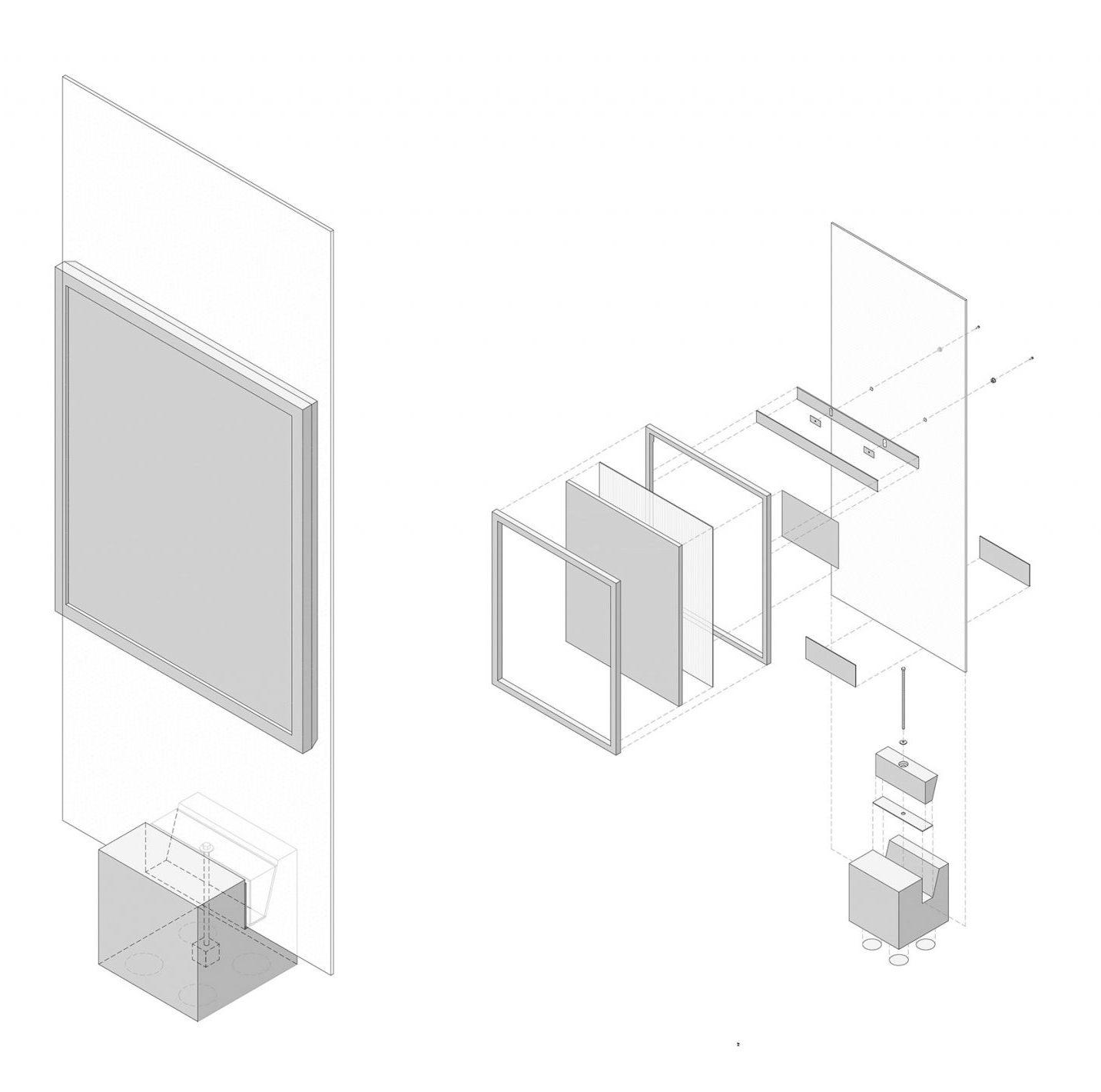
The system, very simple in design, consists of a heavy concrete base to keep the structure stable, and a glass panel, which serves to hold the artwork in a position suitable for viewing. The glass is attached to the base using a wooden wedge and a screw, which applies pressure to the glass, securing it in place. A rubber protective layer is used at the points where the glass contacts the wood and concrete. Some changes were made to the design of the components, but the materials and the principle of operation of the system were strictly maintained. The main adjustments were made to ensure greater strength for the concrete blocks, incorporate the ability to level the structure, enable more efficient and durable wedge tightening, standardize the size and drilling of the glass to allow for artwork replacement without also needing to replace the glass (in the original version, each piece of glass corresponded to a single artwork, with holes in specific positions), increase edge protection for the glass to prevent breakage, and reduce potential unwanted vibrations by using proper shock absorbers.
A steel frame was introduced inside the concrete cube to prevent its rupture. Additionally, an internal stainless steel piece was embedded in the block to house the lower nut and ensure the integrity of the internal channel through which the screw passes, especially at its edges. Recesses were also made on the bottom face of the cube to accommodate the shims needed to level the structure on the museum’s uneven floor, replacing the previously used improvised wooden wedges.
The original dimensions and proportions were maintained, and rough wooden molds were used with conventional concrete to preserve the original appearance.
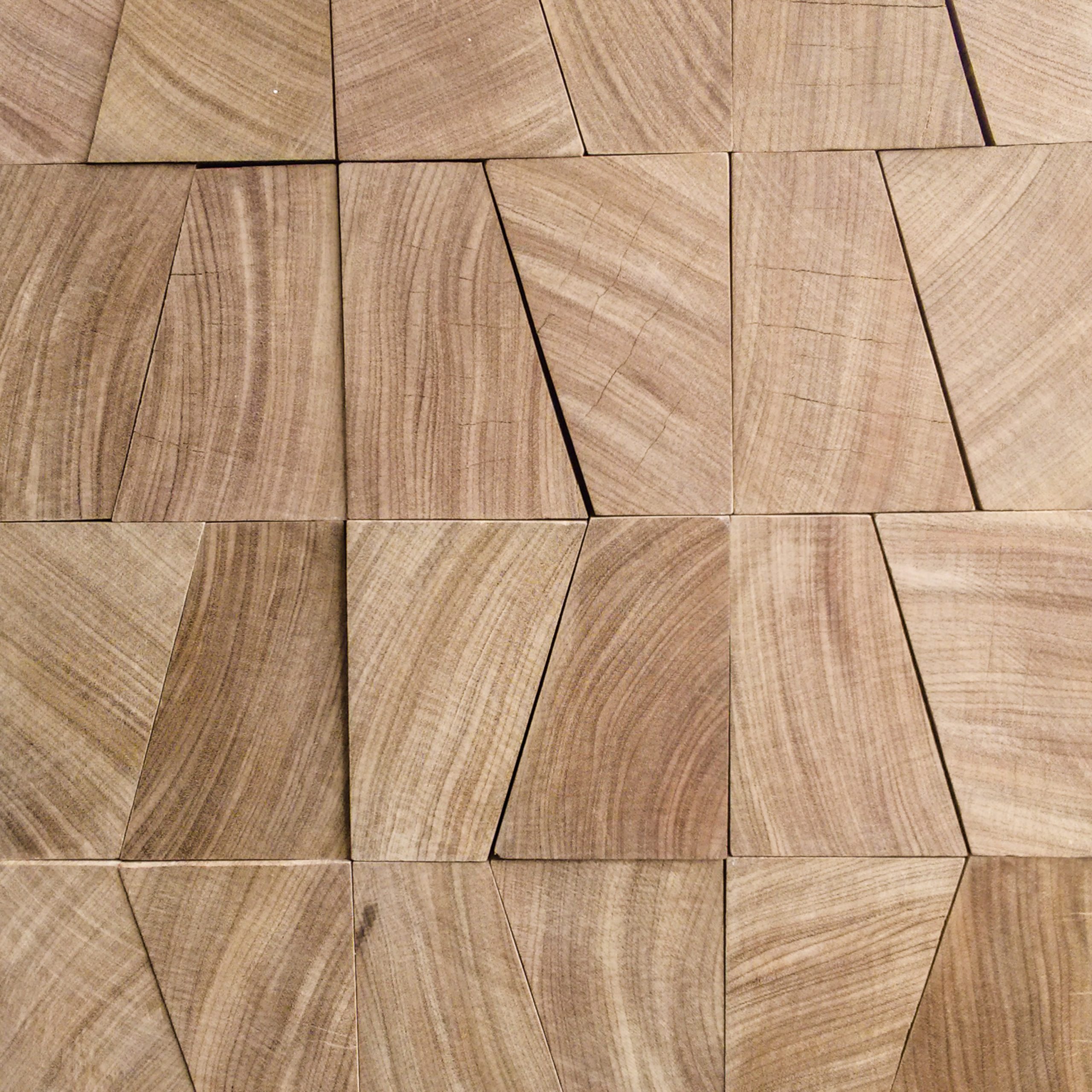
The solid wood wedge received only a recess for the screw head and an enlargement of the central channel to allow the screw to move when pressed. In the original pieces, the contradiction between the wedge’s necessarily diagonal movement and the screw’s vertical position inevitably led to its deformation.
The original system used a screw with its head positioned beneath the cube, in direct contact with the concrete, with the threads extending above the top face of the wooden wedge. A simple nut and washer on top of the wedge allowed the system to be tightened. The new design reverses the position of the screw, keeping the head on top, housed within the wooden wedge, and placing the nut closer to the ground. A washer with an oblong hole on top ensures tightening without damaging the wood and allows the screw to move to absorb alignment differences caused by the wedge’s diagonal movement. At the bottom, the nut is housed in a recess created in the concrete and is fitted with a neoprene washer.
The glass panels follow the original specifications, though with superior quality due to advancements in manufacturing methods and production control. They are tempered, 10 mm thick, and were produced in four widths (0.75 m, 1.00 m, 1.50 m, and 2.20 m— the latter never produced, although it was included in the original sketch), all with the same height (2.40 m).
The drilling maintains a standard distance between the artwork’s display axis and between the two holes for each glass width.
.
The most significant adaptation made to the system was the method of securing the artworks to the glass. To make it more flexible and allow for the display of different artworks on the same support, a stainless steel bar was introduced, fixed to the back frames—wooden pieces installed on the rear of all artworks to be displayed. With oblong holes in the same standard position as the glass drilling, the bar allows for quick and secure mounting and leveling of the artwork. To protect the edges of the holes in the glass and ensure secure fastening, stainless steel bushings were produced to house the screw heads, covered with nylon protection to prevent direct contact between the steel and the glass.
The material for the rubber protective pads on the glass was replaced with elastomeric pads, which offer greater durability and resistance, as the originally used material would dry out and gradually lose elasticity. Shims of various heights were also made from this same material. These pieces, placed under the base in recesses on the bottom face of the concrete cube, allow for leveling the structure and simultaneously absorb vibrations that could be harmful to the artworks. The hardness and vibration absorption properties of the material—typically used in industrial anti-vibration devices—were determined after identifying the predominant frequencies on the museum’s second floor through specialized measurement.
Bibliographic references and research sources
ANELLI, R. L. S. O Museu de Arte de São Paulo: o museu transparente e a dessacralização da arte. São Paulo: Portal Vitruvius, 2009. Disponível em: . Acesso em: 12 ago. 2014.
BARDI, P. M. História do MASP. São Paulo: Instituto Quadrante, 1992.
CAFFEY, S; CAMPAGNOL, G. Dis/Solution: Lina Bo Bardi’s Museu de Arte de São Paulo. Disponível em: . Acesso em 22 jul. 2015.
____________. Explicações sobre o Museu de Arte. O Estado de S.Paulo. 5 abr. 1970.
MASP, Carta Dirigida ao IPHAN, PRE-501/2003, São Paulo, 24 out. 2003.
MIYOSHI, A. Arquitetura em Suspensão: o edifício do Museu de Arte de São Paulo. São Paulo: Armazém do Ipê, 2011.
Technical Specification:
Project Type: Exhibition Design
Project Start: 2015
Project Completion: 2015
Address: Avenida Paulista, 1578, MASP, São Paulo, SP
Area: 2,000 m²
Architectural Design: Martin Corullon, Gustavo Cedroni, Helena Cavalheiro, Juliana Ziebell
Client: MASP
Model Making: Juliana Ziebell, Luis Tavares, Marina Pereira, Marina Cecchi
Production: Marina Moura, Izabela Malzone, Gabriela Fraga, Patrícia Felício
Prototypes: Abividros, Artos Comércio de Móveis Ltda, Stone Pré-fabricados Arquitetônicos Ltda, Tresuno Criações em Concreto, DDF Produções Cinematográficas, ITA Construtora, Hermann Goppert, Mekal Metalúrgica Kadow Ltda, Contato Visual Comércio e Indústria Eireli, Samber Indústria e Comércio, Plastireal Indústria e Comércio Ltda, Elastim Maborin
Final Production: Abividros, Stone Pré-fabricados Arquitetônicos Ltda, Artos Comércio de Móveis Ltda, Mekal Metalúrgica Kadow Ltda, Elastim Maborin
Acknowledgments:Stone, Artos, Mekal, IEME Brasil, Hélio Olga, Abividros, Empório da Madeira
Exhibition Photography: Eduardo Ortega
Installation Photography: Ilana Bessler

